Project Overview
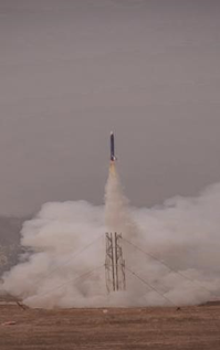
The Garuda Rocket project, spanning from December 2020 to March 2023, aimed to design, fabricate, and launch a single-stage high-power rocket capable of reaching 10,000 feet while carrying a 4kg CubeSat payload. This project was part of the Spaceport America Cup (SA Cup) 2021, an international high-power rocketry competition held in the USA. The rocket incorporated solid propulsion systems, dual parachute recovery mechanisms, and advanced avionics for surveillance experiments and altitude control.
The rocket’s innovative features, structural integrity, and reliable mechanisms contributed to the team winning the “Team Spirit Award” at the event.
Key Features and Specifications
1. Rocket Features
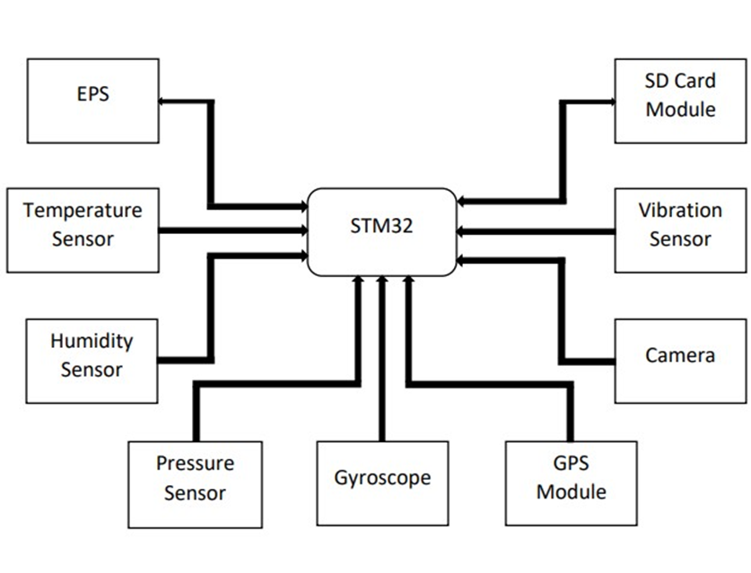
B. Avionics Subsystem
- Telemetry Concept
The telemetry system in Garuda Rocket utilizes a 900 MHz RF communication system within the 33 cm frequency band. This system transmits real-time data, including altitude, velocity, and health of the rocket, to the ground station during flight. By employing error correction protocols, the telemetry system ensures reliable data transmission over long distances, providing critical insights for flight monitoring and decision-making. - SRAD GPS Tracker
The SRAD GPS tracker is built using a Ublox Neo GPS module and operates on a 900 MHz transceiver. It enables real-time tracking of the rocket’s trajectory, position, and altitude. The system was tested successfully over a 1 km range, with plans for full-range testing delayed due to COVID-19 restrictions. The GPS tracker integrates seamlessly with the avionics to ensure accurate flight data is relayed to the ground station. - Upper Avionics
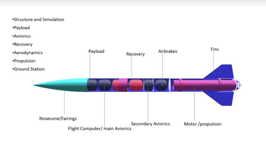
Housed in the nose cone, the upper avionics include redundant barometers, RF transceivers, and the GPS module. This subsystem is primarily responsible for telemetry and payload communication. The nose cone design ensures protection of these sensitive electronics, even during high-stress events such as launch and recovery. - Lower Avionics
The lower avionics subsystem includes components like the BMP 280 barometers, which provide altitude sensing for air brake control. It also acts as a central hub, facilitating communication between propulsion and recovery systems. With redundancy built into its design, this subsystem ensures robust performance under all flight conditions. - EPS (Electrical Power System)
The EPS supplies stable power to the avionics, payload, and recovery systems using LiPo batteries. The system features step-down DC-DC converters to maintain consistent voltage levels. It also includes fail-safe mechanisms to protect against overcurrent and overvoltage, ensuring uninterrupted operation during critical flight phases.
C. Payload System
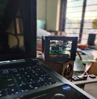
- CubeSat
The 2U CubeSat serves as the primary payload, conducting surveillance experiments using a wide-angle, high-resolution camera and a thermal camera. Its compact design integrates seamlessly into the rocket, with vibration-damping mounts protecting the sensitive instruments during flight. Additionally, the CubeSat provides critical data for perimeter monitoring and payload behavior. - Payload
The payload system weighs 8.9 lbs and includes both functional equipment, like the CubeSat, and a boilerplate mass. This design ensures the rocket’s center of gravity and overall weight are optimized for stability and performance. The payload compartment is thermally insulated and vibration-resistant to safeguard electronics during flight.
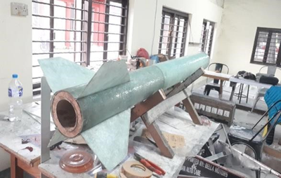
D. Structure System
- Nose Cone
The glass fiber nose cone is aerodynamically optimized to reduce drag and house the upper avionics. It ensures protection of critical components like the GPS module and telemetry equipment during the flight and recovery phases. Its lightweight yet durable construction contributes to overall rocket efficiency. - Body Tube
The rocket’s 87-inch-long body tube is constructed using three layers of 2 mm glass fiber, providing a balance of strength and weight reduction. This structural backbone houses all the subsystems, including propulsion, recovery, avionics, and payload, ensuring durability during high-speed ascent and descent. - Coupler
The coupler connects the rocket’s nose cone, body tube, and recovery system, ensuring a seamless structural interface. Its design evenly distributes the forces experienced during flight, preventing localized stress points and enhancing the rocket’s overall stability. - Inner Tube
The inner tube is designed to support the propulsion system and recovery mechanism. It provides a sturdy, heat-resistant framework for the motor while ensuring the structural integrity of the rocket under extreme temperatures and pressures. - Center Ring
The center ring is a critical structural component that provides mounting points for the fins, avionics, and recovery system. Its lightweight yet robust design ensures even weight distribution, contributing to the rocket’s aerodynamic stability during flight. - Fins
The rocket is equipped with four carbon fiber fins, each with a semi-span of 5 inches. These fins are designed to enhance aerodynamic stability, ensuring a smooth trajectory and minimizing wobbling during flight. Their lightweight construction reduces drag while maintaining high structural integrity.
E. Recovery System
- Recovery System
The recovery system employs a dual deployment mechanism for safe descent. A drogue parachute stabilizes the rocket at high altitudes, while the main parachute ensures a gentle landing. Both parachutes are deployed using a spring-loaded system to ensure reliability. - Drogue Parachute Deployment
The drogue parachute is deployed at 10,000 feet using a spring mechanism with a force of 8.736 N/mm. It stabilizes the rocket and reduces its descent rate to 88.6 ft/s, preparing it for main parachute deployment. - Shock Cord
A nylon shock cord with a load capacity of 100 lbs connects the parachutes to the rocket. It is designed to withstand the forces exerted during deployment and descent, ensuring secure attachment throughout recovery. - Main Parachute Deployment
The main parachute is released at 1,500 feet, decelerating the rocket to a descent rate of 16.8 ft/s. The deployment is controlled using a nylon cord and a spring-assisted system to ensure reliability. - General Parachute Design
The parachutes are made of durable nylon fabric and feature a modular design for easy maintenance. Their construction ensures stability during descent, minimizing oscillations and impact forces. - Connection of Recovery System
The recovery system is securely connected to the rocket using reinforced bulkheads and connectors. This design ensures consistent and reliable performance during deployment. - Assembly of Parachute Compartment
The parachute compartment is designed for easy assembly and maintenance. Its modular structure allows for quick adjustments and ensures all components remain secure during flight.
F. Simulation and Control
- Drag Control System
The rocket features air brakes that are deployed after motor burnout to control altitude. These brakes are managed by redundant barometers in the lower avionics, ensuring precision in maintaining the target apogee of 10,000 feet. - Simulations for the Rocket Body
Simulations conducted using Ansys and OpenRocket optimized the rocket’s aerodynamic performance. The predicted apogee was calculated at 10,350 feet, with a maximum velocity of 1021 ft/s and an acceleration of 11.8 G during boost.
G. Propulsion Subsystem
- COTS Motor Details
The rocket uses an Aerotech M2400T solid motor with a total impulse of 7716.5 Ns. This M-class motor generates an average thrust of 2400 N over a burn time of 3.2 seconds, providing the necessary propulsion to achieve the target apogee. - SRAD Motor Propellant Details
A sugar-based SRAD motor was developed and tested for research purposes. While not used in the competition, it provided valuable insights into motor design and manufacturing. - Thrust Force Calculation Details
The liftoff thrust-weight ratio was calculated at 11:1, with a rail departure velocity of 109 ft/s. These metrics ensured the rocket’s stable and efficient launch.
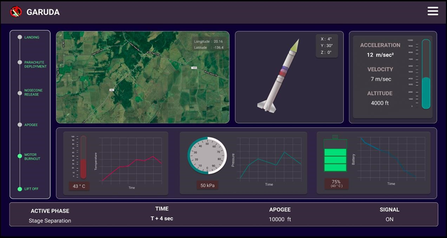
H. Ground Station Subsystem
- Goals and Outlook
The ground station provides real-time telemetry, GPS tracking, and communication throughout the flight. It serves as the primary interface between the rocket and the mission control team. - Implementation
The system uses a 900 MHz RF link for communication, ensuring reliable data transfer. - Desktop Application
A dedicated desktop interface displays telemetry data, including altitude and trajectory, for mission monitoring. - Mobile Application
A portable mobile app enables field teams to track the rocket in real time during the flight and recovery phases. - Web Application
The web-based application provides remote access to live flight data, ensuring stakeholders can monitor the mission from any location.
Design and Mechanism
1. Structural Design
- Developed a glass fiber rocket body, optimizing strength-to-weight ratio.
- Designed center rings to support critical components, including fins, avionics, and motors.
2. Stage Separation Mechanism
- Introduced a spring-loaded stage separation system with three springs and a custom bearing mechanism.
- Replaced traditional shock bolt designs with a reliable and efficient separation method, tested across 10 consecutive launches.
3. Recovery System
- Dual parachute system designed for safe recovery.
- Drogue parachute: Stabilization at high altitude.
- Main parachute: Final descent at low altitude.
4. Manufacturing Techniques
- Utilized advanced manufacturing tools, including:
- SolidWorks for structural design.
- 3D Printing and laser cutting for components.
- Carbon fiber and glass fiber molding for structural parts.
- Plasma cutting for precise recovery and separation mechanisms.
My Responsibilities and Contributions
- Structural System Design:
- Designed and optimized the glass fiber rocket body to ensure lightweight yet durable construction.
- Integrated center rings for component support, enabling efficient assembly of fins, motors, and avionics.
- Stage Separation Mechanism:
- Developed and tested a spring-loaded mechanism to ensure reliable stage separation and parachute deployment.
- Conducted multiple tests to validate the system’s performance under various conditions.
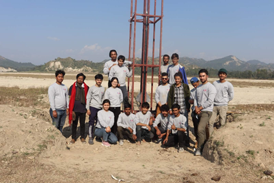
- Team Collaboration:
- Worked with a 15-member multidisciplinary team to integrate avionics, telemetry, propulsion, payload, and structural systems.
- Manufacturing and Assembly:
- Fabricated components using 3D printing, laser cutting, and plasma cutting techniques.
- Conducted carbon fiber and glass fiber molding for structural parts.
- Testing and Validation:
- Conducted 5 test launches and 15 static fire tests of the solid-propellant engine.
- Iterated designs based on test feedback to improve performance.
- Engineering Documentation:
- Completed Engineering Change Notices/Requests (ECN/ECR) for iterative design improvements.
Achievements
- Successful Launch: Achieved a target altitude of 10,000 feet with a 4kg CubeSat payload.
- Award Recognition:
- Won the “Team Spirit Award” at the Spaceport America Cup 2021.
- Innovative Solutions:
- Designed and implemented a reliable stage separation system that outperformed traditional methods.
- Manufacturing Excellence:
- Utilized cutting-edge manufacturing processes to produce lightweight and durable components.
Impact and Future Scope
Impact
- Advanced the use of composite materials in high-power rocketry for strength and weight optimization.
- Demonstrated the feasibility of spring-loaded separation mechanisms, enhancing reliability.
- Contributed to international rocketry competitions, representing innovation in Nepal.
Future Scope
- Enhanced Payload Capabilities: Integrate deployable CubeSats for more complex experiments.
- Automation: Develop smart avionics for real-time in-flight adjustments.
- Higher Altitude Goals: Extend performance to reach 20,000+ feet in future iterations.
Test Report Appendix for the Garuda Rocket Project
This appendix provides a summary of the various subsystem tests conducted during the Garuda Rocket Project, highlighting the functionality, purpose, and results for each test.
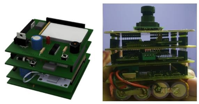
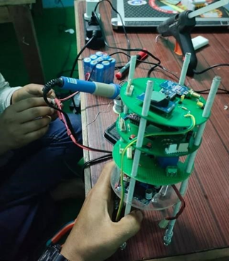
1. Avionics Assembly and Functionality Test
- Subsystem: Avionics
- Date and Time: 5th December, 2020
- Type: SRAD
- Purpose:
- Assemble and test functionality of the avionics components.
- Sensor calibration and testing.
- Location: Kathmandu University
- Remarks: Due to COVID-19 shipment restrictions, the Startologger CF COTS altimeter was unavailable.
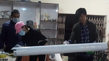
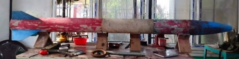
2. Rocket Body Fabrication and Durability Test
- Subsystem: Structure
- Date: 1st December, 2020
- Specifications:
- Total Length: 2209.8 mm
- Center of Gravity (CG): 52 inches from nose-cone tip
- Center of Pressure (CP): 63 inches from nose-cone tip
- Diameter: 6.1 inches
- Material: Glass Fiber (3 layers, 2 mm thickness)
- Type: SRAD
- Purpose: Manufacture and test the strength of body tubes.
- Location: Kathmandu University
- Remarks: Durability tests (linear and radial strength) were conducted at a universal tensile testing lab.
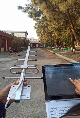
3. GPS Tracker/Ground Station Test
- Subsystem: Ground Station
- Date: 10th February, 2021
- Materials Used: Yagee Antenna, Transceiver XBEE 900 MHz, Ublox Neo GPS
- Type: SRAD
- Purpose: GPS tracker and telemetry test.
- Test Distance: 1 km
- Location: Thapathali Campus
- Remarks: A short-range test was completed successfully. Full-range testing was delayed due to COVID-19 lockdown.
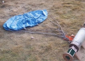
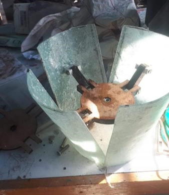
4. Recovery Ground Test
- Subsystem: Recovery
- Date: 5th February, 2021
- Materials Used: Spring-loaded mechanism
- Type: SRAD
- Purpose: Check recovery deployment.
- Separation Distance: 1 meter
- Time to Separate and Release: 10 seconds
- Location: Kathmandu University
- Remarks: A pair of loaded springs failed to push the nose cone sufficiently, leading to a redesign with four springs.
5. Software/User Interface Test
- Subsystem: Avionics
- Date: 5th February, 2021
- Materials Used: GPS Module
- Type: SRAD
- Purpose: Test GPS tracker and avionics software.
- Location: Kathmandu University
- Remarks: Data was successfully obtained, and the test was completed without issues.
6. Payload Assembly and Functionality Test
- Subsystem: Payload
- Date: 15th March, 2021
- Materials Used: Sensors, GPS Module, Camera, Accelerometer
- Purpose: Assemble and test the 2U CubeSat integrated with the rocket.
- Location: Orion Space
- Remarks: The first iteration of the payload was successfully tested.
7. Air Brake System and Wind Tunnel Test
- Subsystem: Structure
- Date: 20th December, 2020
- Materials Used: Air brake assembly
- Type: SRAD
- Purpose: Test air brake functionality and rocket body aerodynamics in a wind tunnel.
- Location: Institute of Engineering, Pulchowk Campus
- Remarks: Manufacturing delays due to COVID-19 lockdown.
8. Rocket Weight Test
- Subsystem: Structure
- Date: 22nd April, 2021
- Materials Used: Fully assembled rocket components (body tube, nose-cone, payload, motor, etc.)
- Purpose: Measure the weight of the fully assembled rocket.
- Location: National Innovation Centre
- Remarks: The total weight was found to be 22.2264 kg.
9. Rocket Vibration Test
- Subsystem: Structure
- Date: 25th April, 2021
- Materials Used: Assembled rocket body
- Type: SRAD
- Purpose: Test the durability and strength of the rocket under vibration.
- Location: National Innovation Centre
- Remarks: Test results pending.

10. Static Fire Test
- Subsystem: Propulsion
- Date: 1st January, 2021
- Materials Used: Motor chamber, nozzle, test stand, load cell sensor, ignitor, propellant
- Type: SRAD
- Purpose: Test the strength and durability of the motor.
- Location: National Innovation Centre
- Remarks: Irregular grain configurations and nozzle dimensions caused initial failures. Full-scale tests achieved the required thrust for the expected apogee.
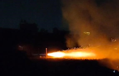
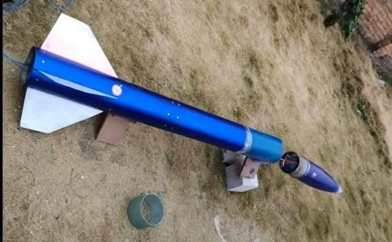
11. 1st Test Launch
- Subsystem: Structure, Propulsion, Recovery, Avionics, Payload, Ground Station
- Date: 20th March, 2021
- Type: SRAD
- Purpose: Test the functionality of all subsystems and check if the rocket reaches the expected apogee.
- Location: Dhanusha
- Remarks: Due to nozzle melting, the rocket’s trajectory deviated after reaching 200 meters